Install the sensors
Remove all keys
Remove all keys from the key frame.
Connect the sensorboard pairs
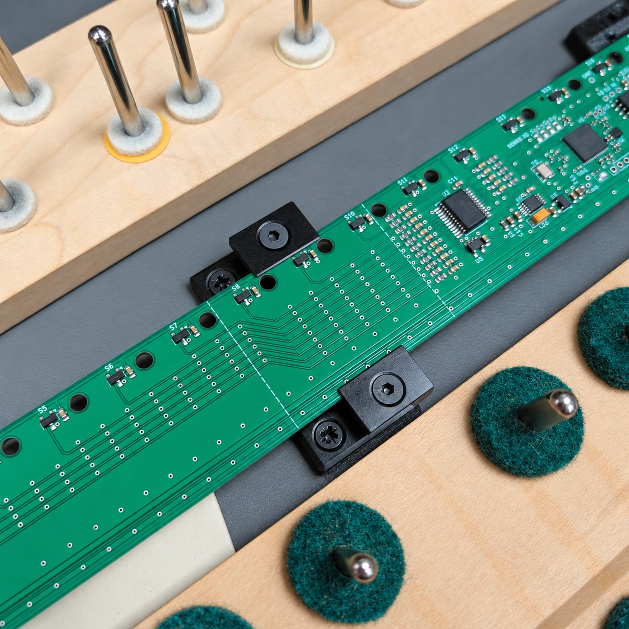
The installation uses four sensorboards. Connect boards 1 and 2 to form the left-hand pair, and boards 3 and 4 to form the right-hand pair.
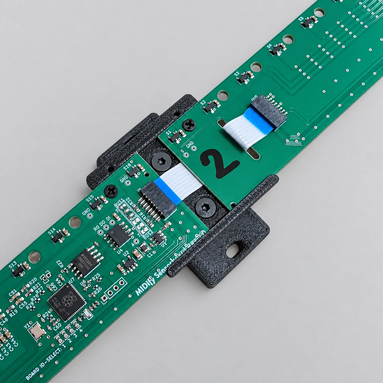
Connect the FPC cables between the boards in each pair before fastening them together. Then secure each pair to the support brackets using 2.3 × 5 mm countersunk screws so that the two boards are mechanically joined as well as electrically connected.
Position the left-hand sensorboard pair
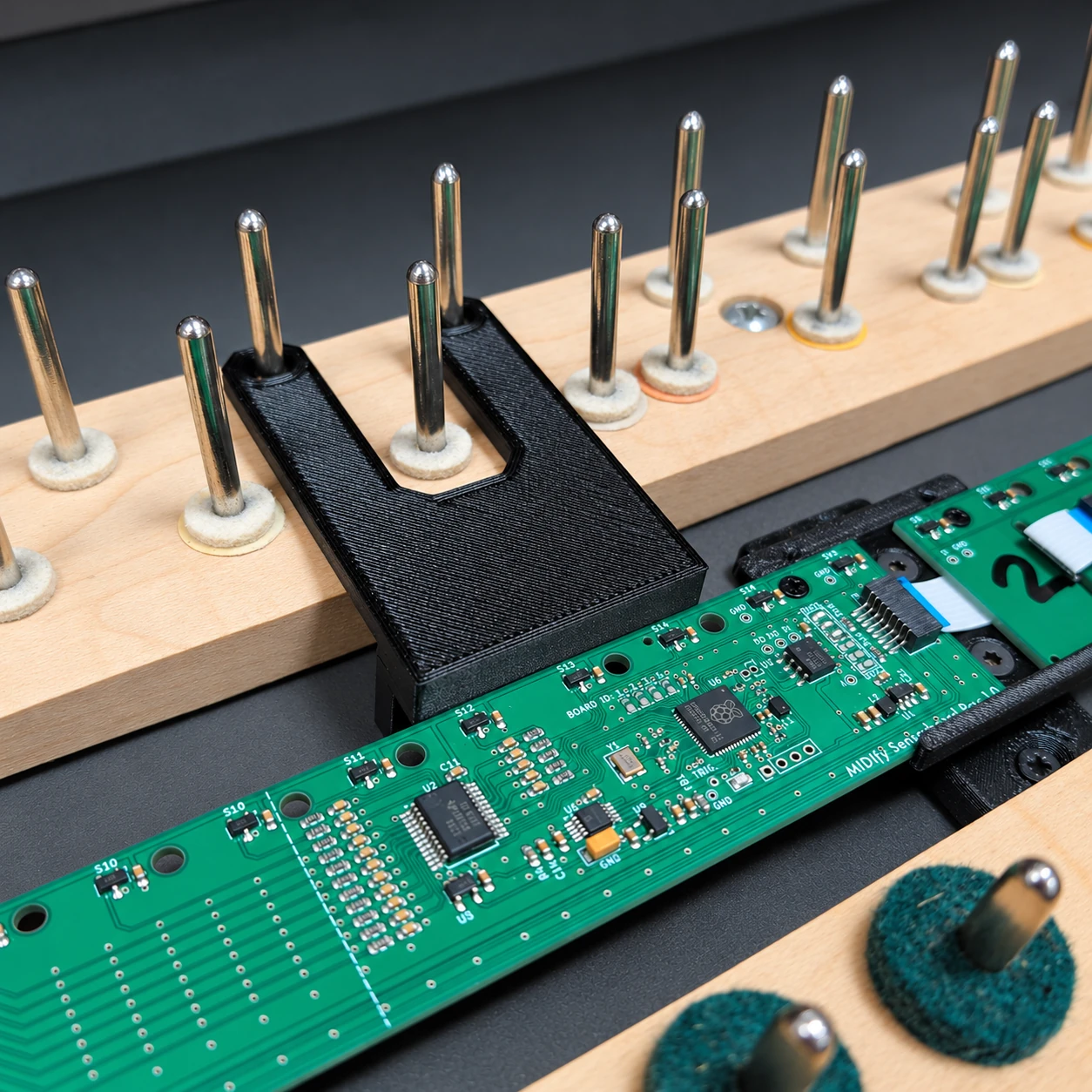
Fit the two positioning jigs onto the key pins for the black keys on the left-hand side of the keyboard. Place the left-hand sensorboard pair in the instrument and move it against the upper step of both jigs to set its front-to-back position.
Align and secure the left-hand sensorboard pair
Visually align the sensors with the balance rail pins to set the left-to-right position of the pair. Keep the boards against the upper steps of the positioning jigs while aligning them.
It is normal for some sensors not to line up exactly with their corresponding balance rail pins or the centres of the keys. Position each pair so that these deviations are distributed as evenly as possible across its keys. Check that every magnet holder can still be mounted on its key with the magnet aligned over the corresponding sensor.
Once aligned, secure the support base plates to the instrument's case floor using 3 × 16 mm countersunk screws. Fit a board guide onto each end of the pair: one at the left-hand end and one at the right-hand end.
Position, align and secure the right-hand sensorboard pair
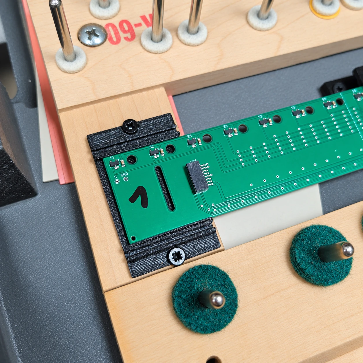
Move the two positioning jigs onto the black-key pins on the right-hand side. Place boards 3 and 4 in the instrument and move the pair back against the upper step of both jigs.
While fitting the right-hand pair, connect board 2 to board 3 using the FPC cable to join the two pairs electrically.
Insert the left-hand end of this pair into the board guide already fitted to the right-hand end of the left-hand pair. Visually align the sensors with the balance rail pins, keeping the boards against the jigs. Then secure the support base plates to the case floor using 3 × 16 mm countersunk screws.
Fit a board guide onto the right-hand end of the pair. The guide between the two pairs is shared; no additional guide is needed there.
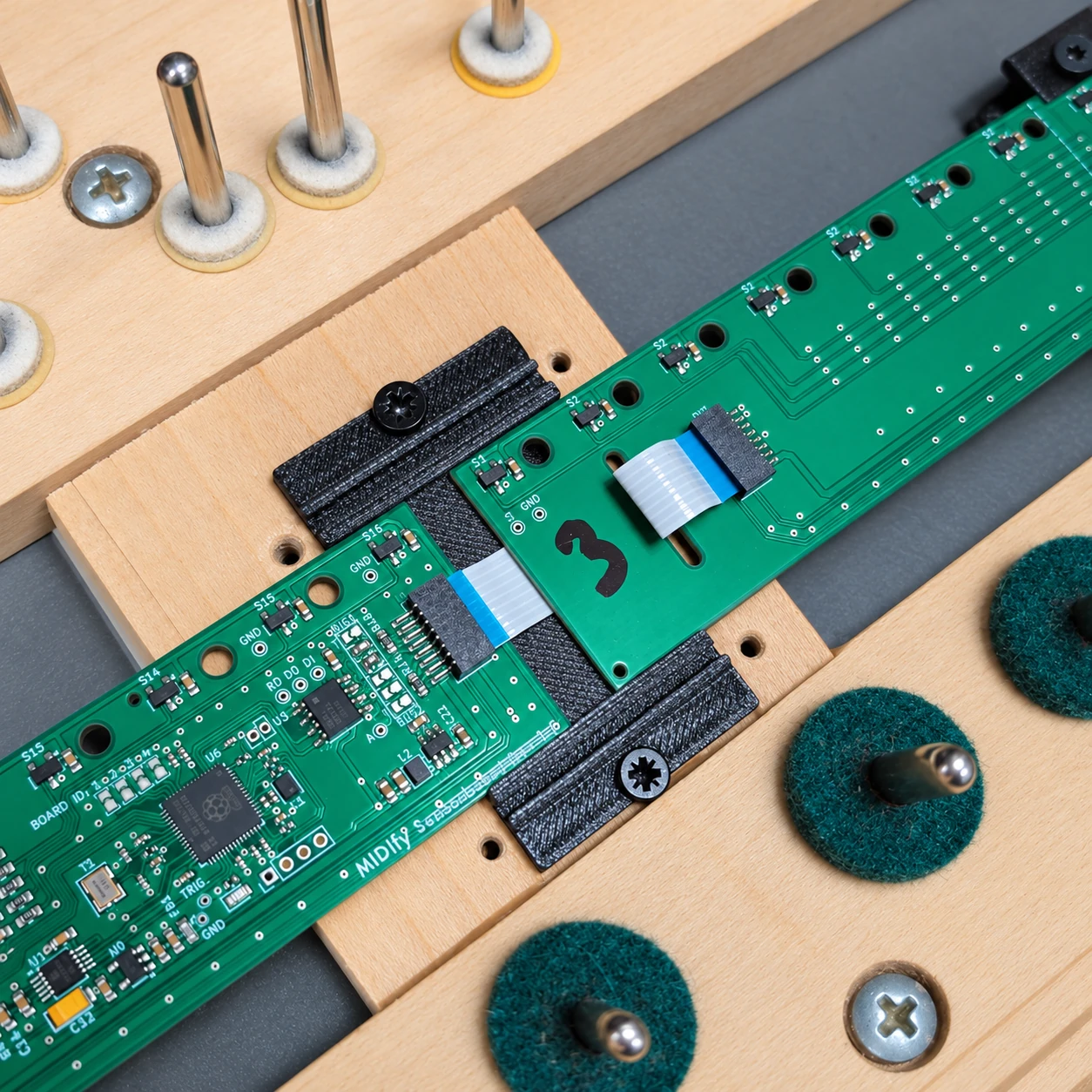
Secure the board guides
Secure each of the three board guides to the key frame using two 3 × 10 mm countersunk screws.
Fit the sensorboard standoffs
To prevent the sensorboards from bending upwards, fit two standoffs at the centre of each board, one on each long edge. This gives eight standoffs across the four sensorboards.
Hook the upper part of each standoff onto the board so that the board edge sits in its groove. Secure the standoff base plate to the instrument's case floor using a 3 × 16 mm countersunk screw.
The height at each standoff can be adjusted using its hex-socket adjustment screw.