Install the electronics
Remove the right cheek block
Remove the two screws securing the right cheek block: one from the top and one from the front. Remove the cheek block and keep the screws for reassembly.
Prepare the MIDIfy cheek block
The MIDIfy cheek block comes preassembled. Connect the 20 cm 8-pin FPC cable to the cheek block with the blue side facing the top of the connector. Plug the USB cable into the USB socket inside the cheek block.
The other end of the USB cable will be connected to the pin header on the mainboard when the cheek block is installed.
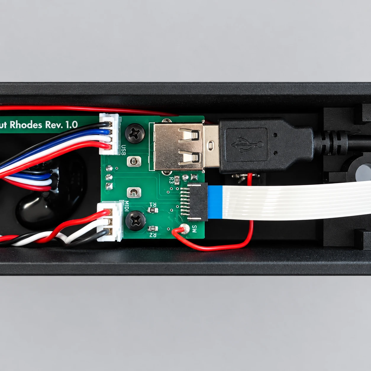
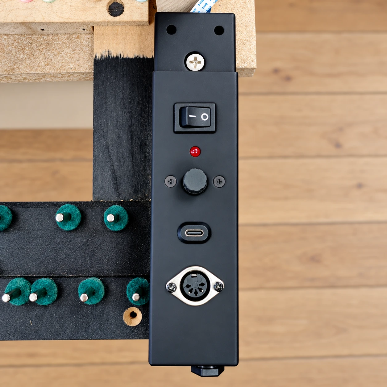
Install the MIDIfy cheek block
Fit the MIDIfy cheek block in place and secure it with the two screws removed earlier. Take care not to pinch or damage either cable during installation.
Install the mainboard
1. Position the mainboard
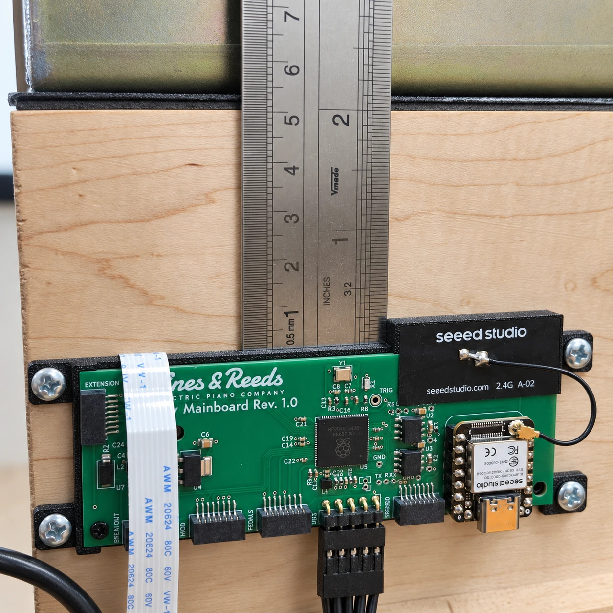
Position the mainboard on the right-hand support with its connectors facing downwards.
Connect the free end of the 20 cm 8-pin FPC cable from the cheek block to the connector labelled BREAKOUT on the mainboard.
Use the positioning instructions for your support type:
Wooden supports
Position the top edge of the mounting bracket 5 cm below the top edge of the support. Align the front edge of the bracket flush with the front edge of the support.
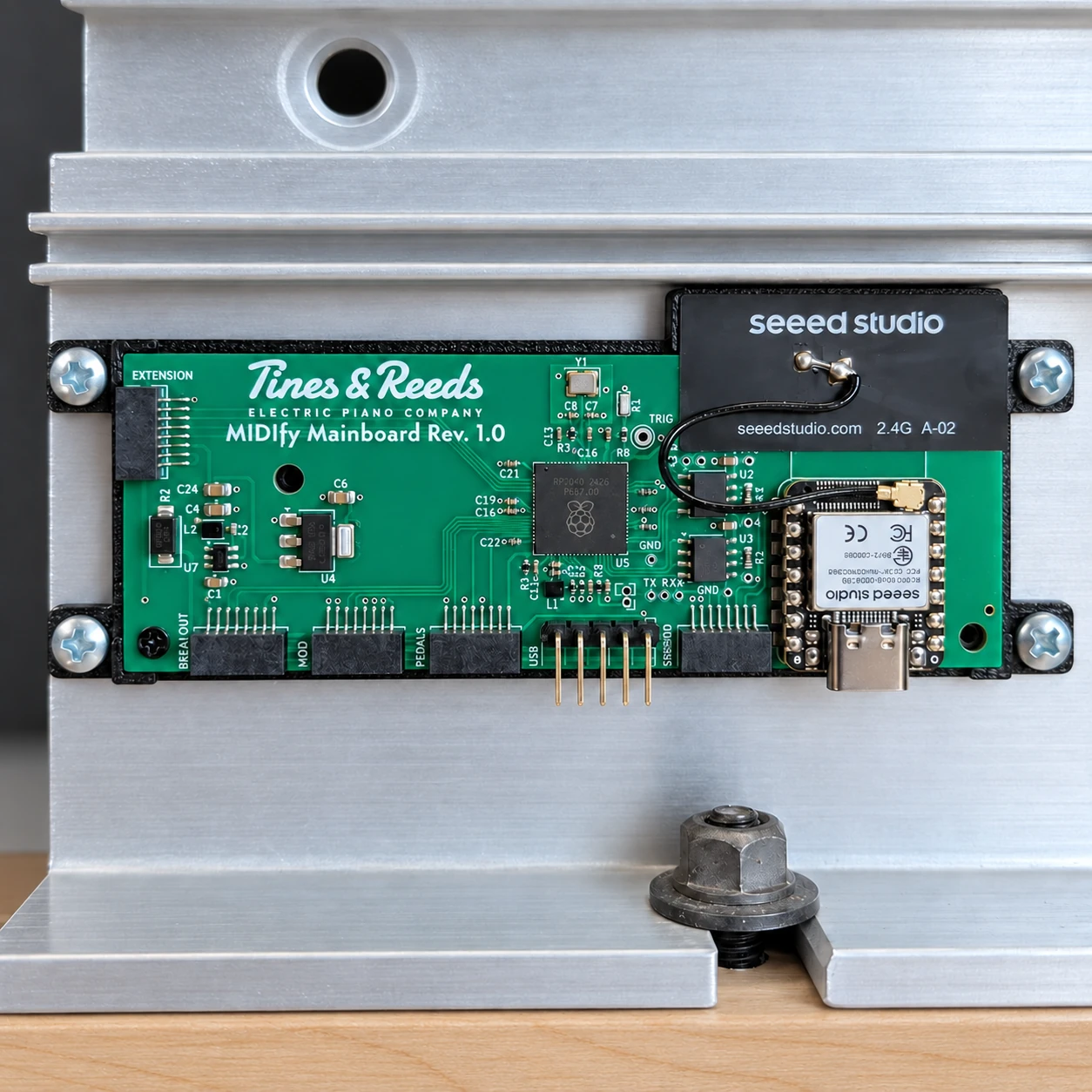
Aluminium supports
Position the mainboard as shown in the photo below.
2. Secure the mainboard
Drill pilot holes for all four mounting screws: use a 3.2 mm drill bit for aluminium supports or a 2.5 mm drill bit for wooden supports.
Secure the mainboard bracket to the support using four 3.5 × 10 mm pan-head screws.
3. Connect the USB cable and route the cables
Connect the USB cable to the USB pin header on the mainboard. Make sure the black wire is aligned with the pin marked G.
USB cable routing (recommended)
We recommend routing and securing the USB cable using a cable clamp (not provided), as shown in the mainboard photo below.
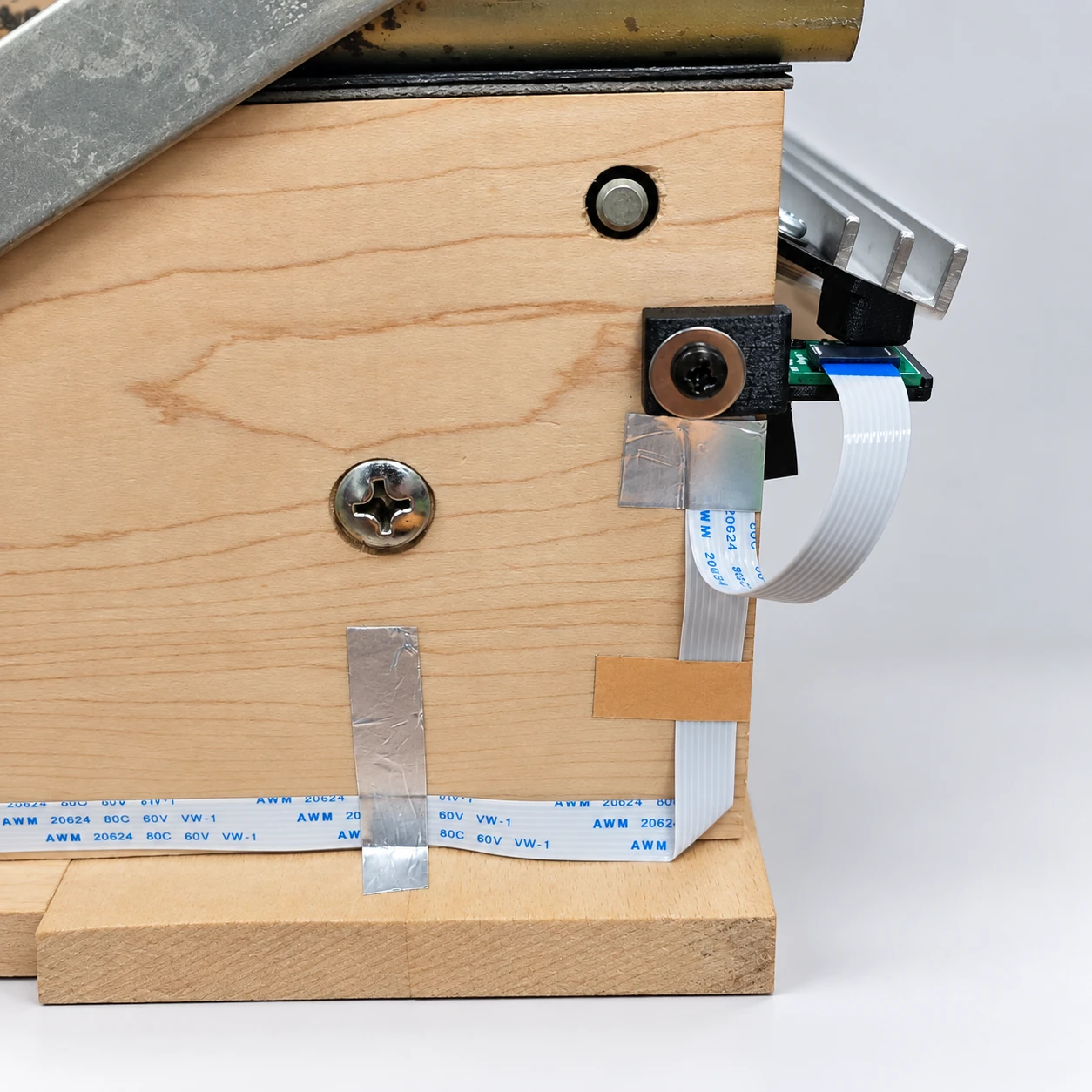
FPC cable securing (optional)
Optionally, secure the FPC cable to the support with the supplied aluminium or copper tape. Before applying the tape, clean and degrease the contact surface with isopropyl alcohol and allow it to dry.
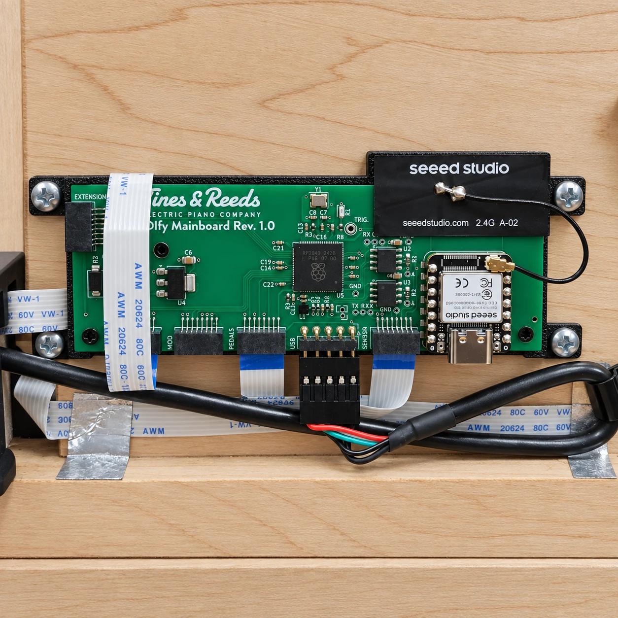
Cable routing overview. The photo also shows the sustain and keyboard sensor cables, which are connected in the following steps.
Mount the sustain sensor bracket
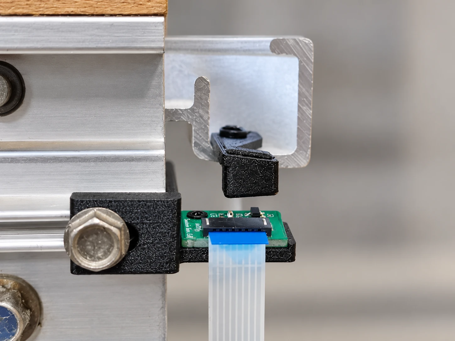
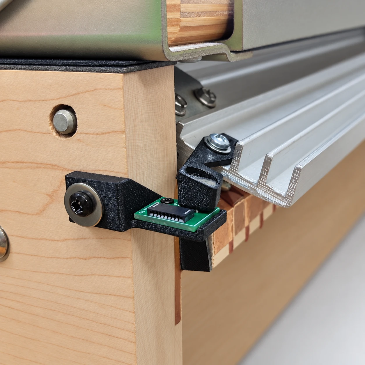
For wooden supports, position the top edge of the sensor bracket 25 mm below the top edge of the support as an initial position. Drill a 2.5 mm pilot hole and secure the bracket with one 3.5 × 16 mm pan-head screw and a matching washer.

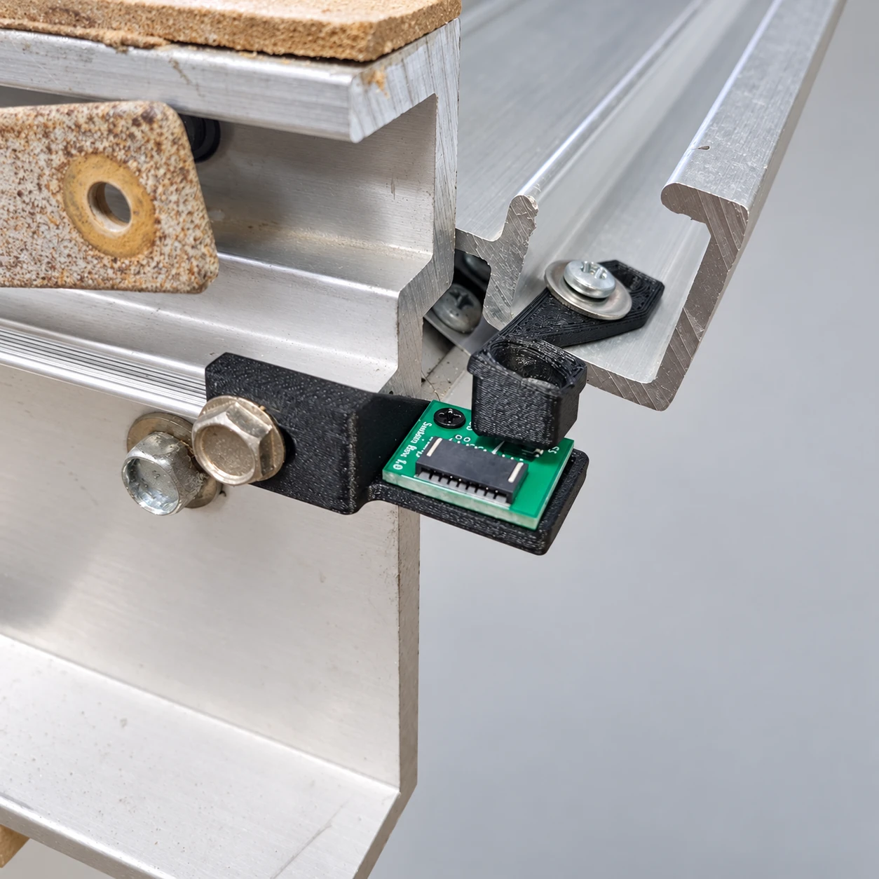
For aluminium supports, secure the sensor bracket by screwing the supplied tine screw into the groove in the aluminium support.
Mount the sustain magnet holder
Place the magnet holder on the damper rail and align it centrally with the sustain sensor. Drill a 3.2 mm pilot hole and secure the magnet holder with one 3.5 × 10 mm pan-head screw and a matching washer.
Connect the sustain sensor
Connect the 40 cm FPC cable to the sustain sensor with the blue side facing upwards. Connect the other end to the connector labelled PEDALS on the mainboard.
Prepare the keyboard sensor connection
Plug a 20 cm FPC cable into the connector labelled SENSOR on the mainboard. Route the free end towards the front of the instrument and leave it disconnected for now. It will be connected to the sensor board chain later.
Reinstall the key frame
Place the key frame back into the instrument case and secure it using the screws removed earlier. Make sure the key frame, especially the balance rail, sits flush against the case.
Additional balance rail fastening (recommended)
On later Rhodes models, the key frame may be secured only at the left and right sides, allowing the balance rail to bow upwards. If this occurs, we recommend securing the balance rail to the case with at least two additional screws inserted from underneath the case into the balance rail.