Install the sensor rail
The installation procedure is the same for 73-key and 88-key Rhodes models. Use the sensorboards supplied for your instrument.
Remove all keys
Remove all keys from the key frame.
Join the sensor rail sections
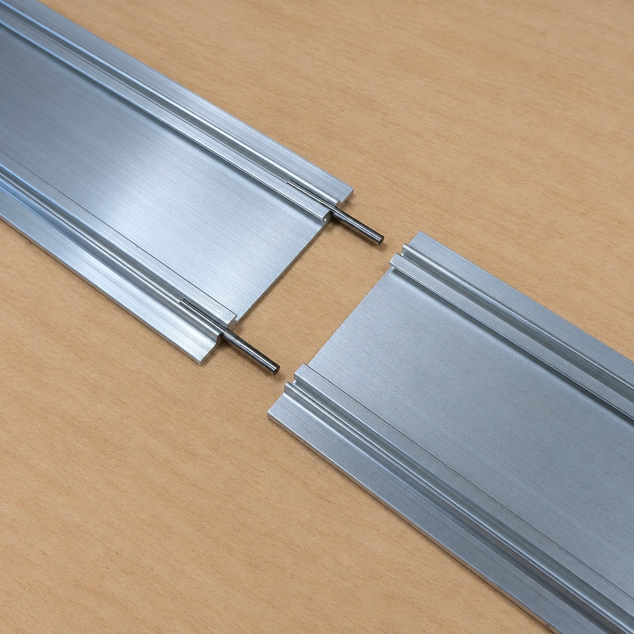
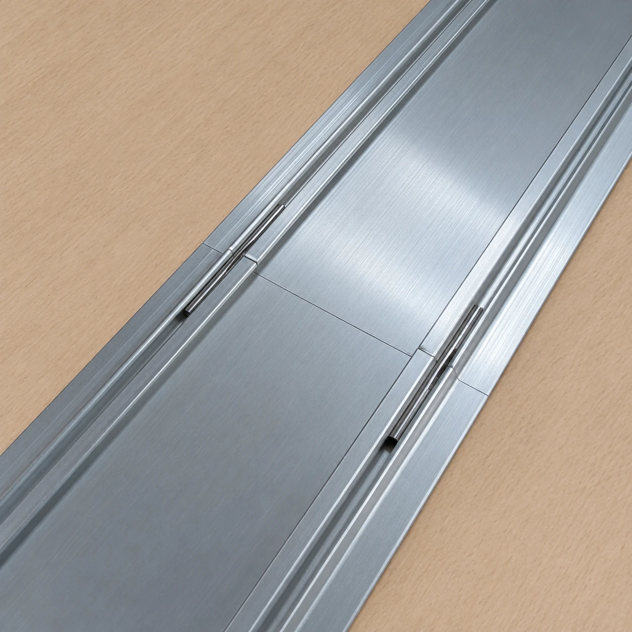
The aluminium sensor rail is supplied in several sections. Align the dowel pins with the matching channels in the next section and tap the sections together until the joint is fully closed. Repeat at all joints.
Cut the rail to length
The sections are supplied in fixed lengths. Use a hacksaw to shorten the rail to fit your instrument. Remove the cutting debris before fitting the sensorboards.
Insulate the sensor rail
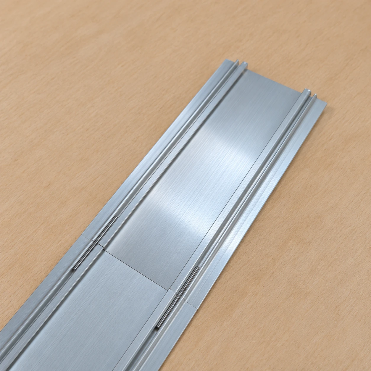
Cover the inside floor of the assembled rail with masking tape before inserting the sensorboards. The tape must prevent electrical contact between the circuit boards and the aluminium profile.

Prepare and insert the sensorboard chain
Starting with sensorboard 2, insert a 5 cm, 8-pin FPC cable into its OUT connector with the blue side facing up. Feed the free end through the slot in the circuit board and connect it to the IN connector on sensorboard 1.
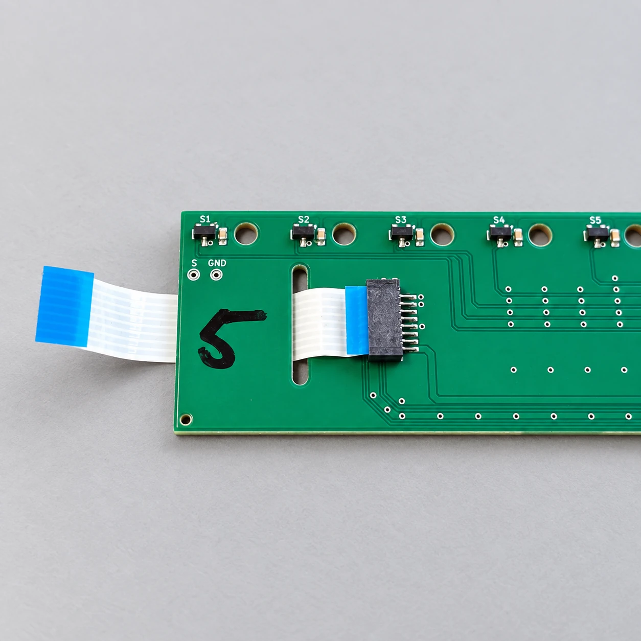
Repeat for the remaining boards, connecting each board’s OUT cable to the previous board’s IN connector. Connect all sensorboards before inserting them into the rail. The protruding FPC cable can be folded over to the left.
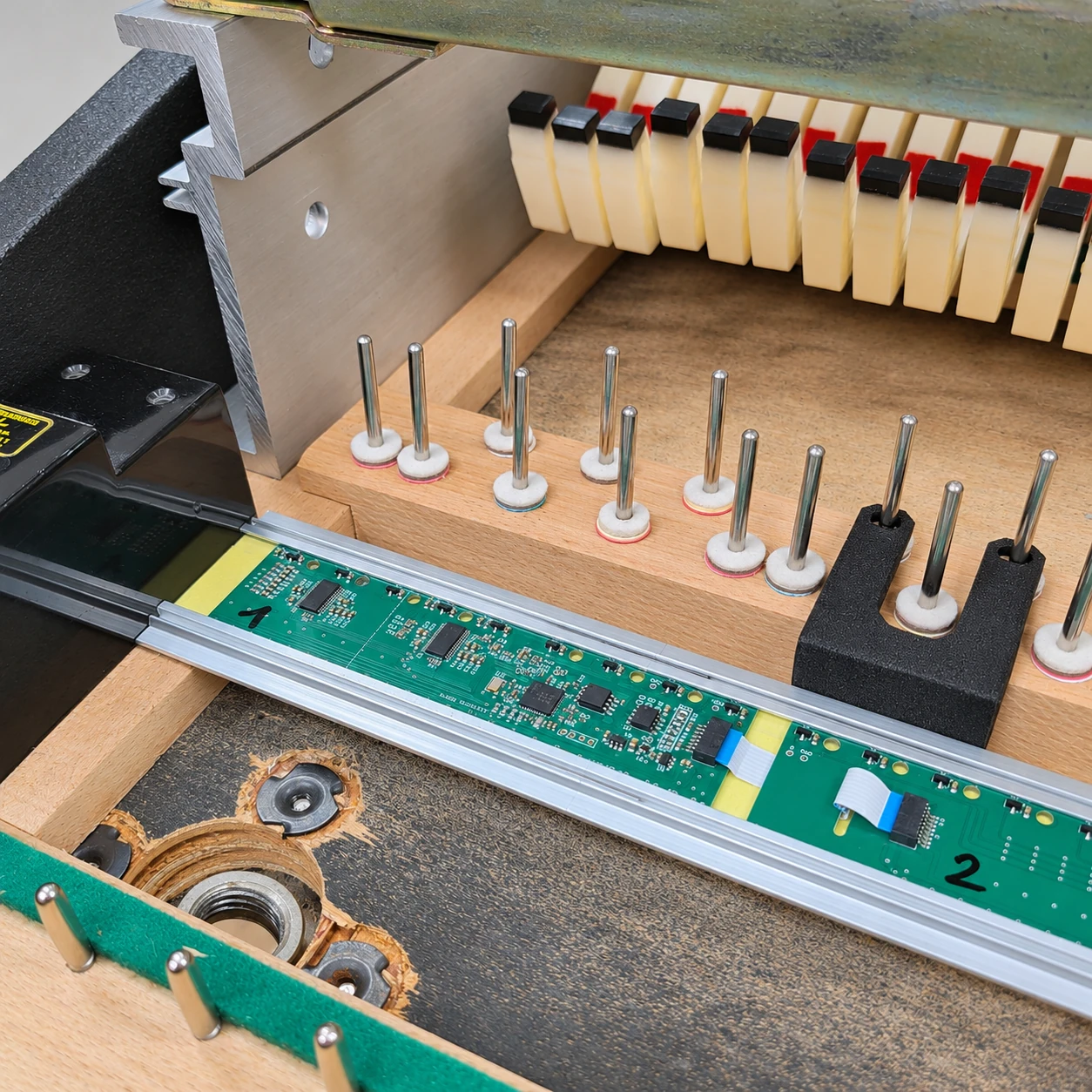
Slide the connected chain into the aluminium rail from the right. Sensorboard 1 must end up at the left-hand end, with the remaining boards in numerical order towards the right.
Set the front-to-back position
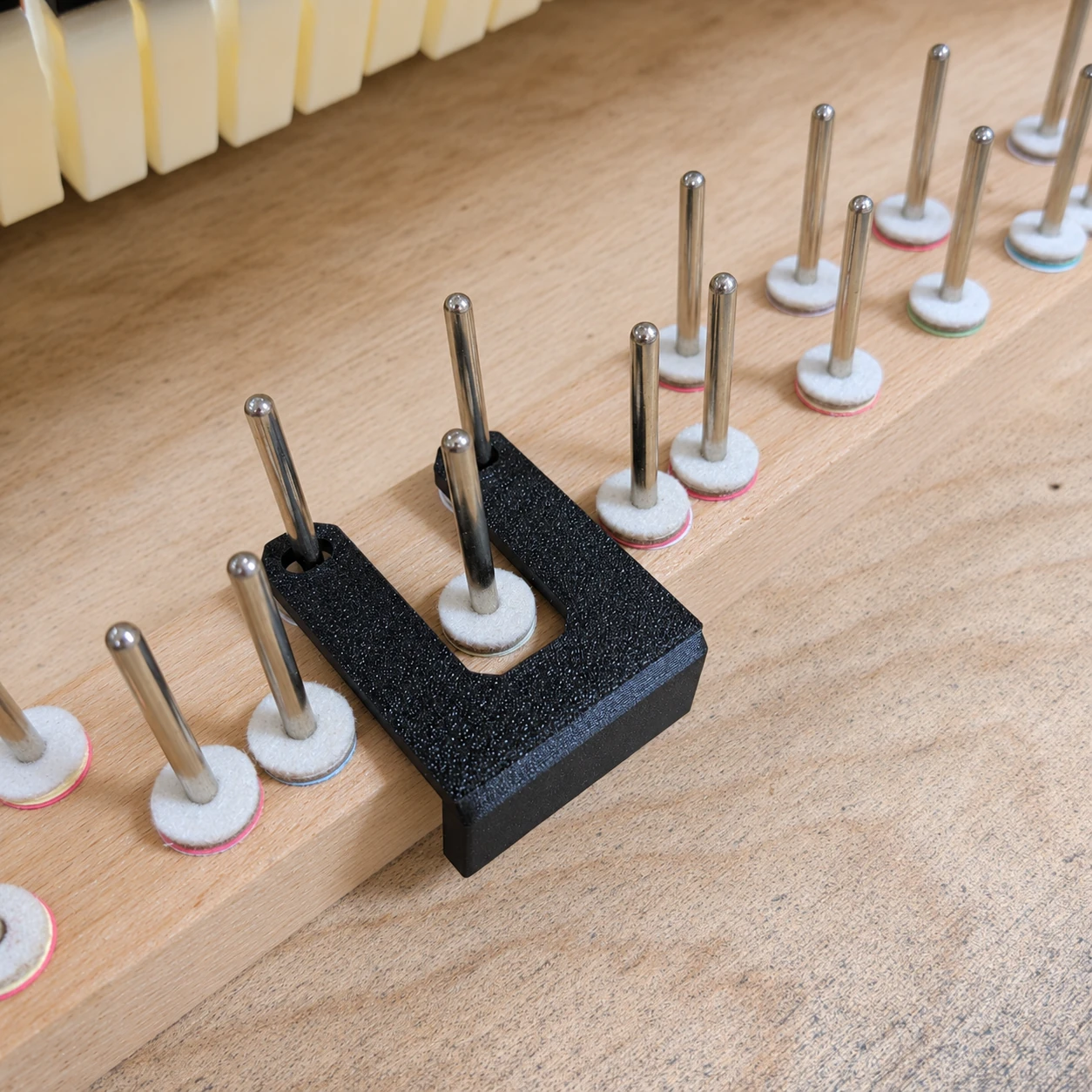
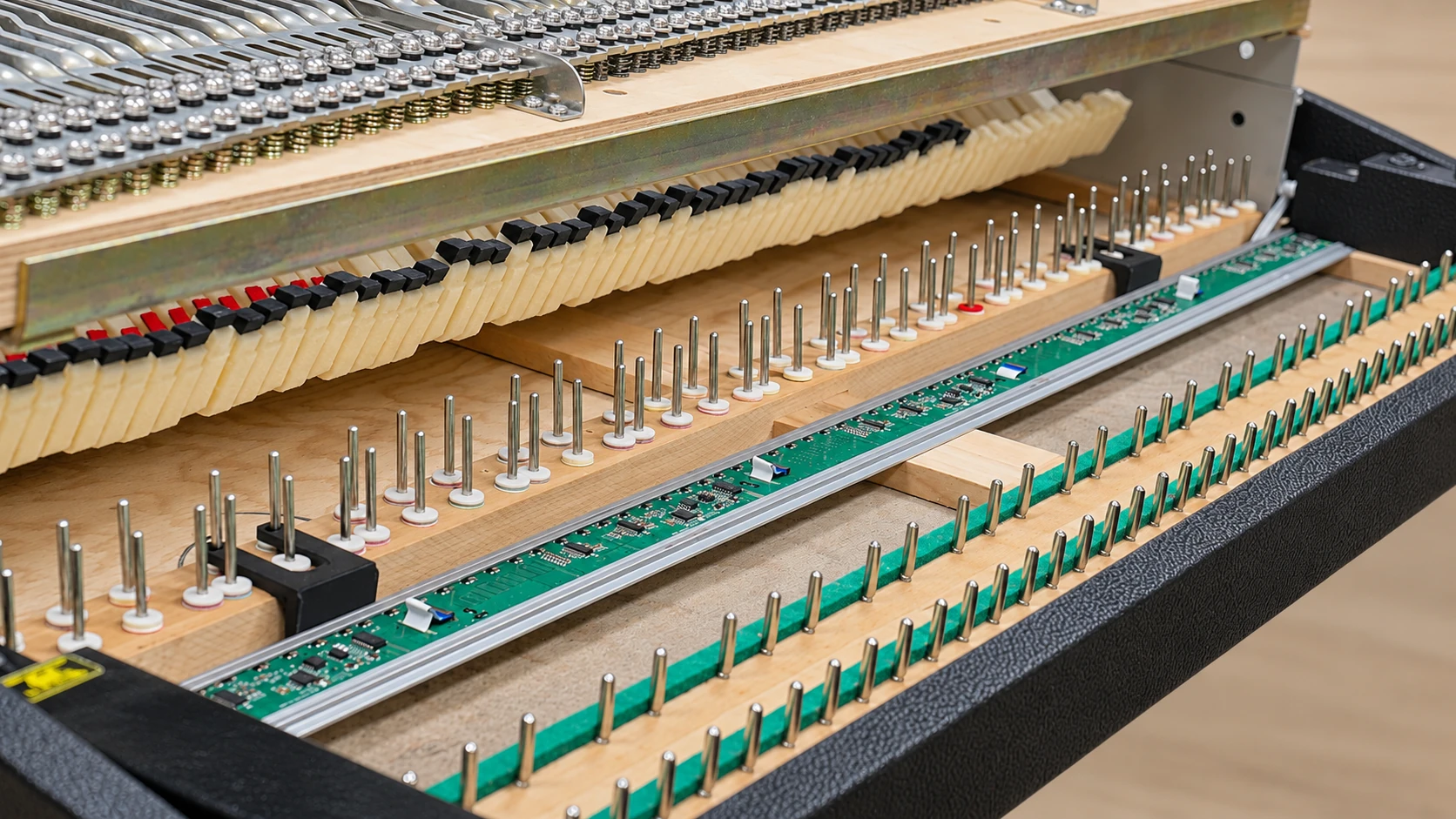
Place the two positioning jigs onto the black-key pins. Put the assembled rail with its sensorboards into the instrument and move it back until it rests against both jigs. Keep the left-hand end of the rail against the left cheekblock.
Align and secure sensorboard 1
Align the sensors on sensorboard 1 with the balance rail pins as closely as possible. It is normal for some of the sensors not to line up exactly with their corresponding pins. Position the board so that the deviations are distributed as evenly as possible across all sensors.
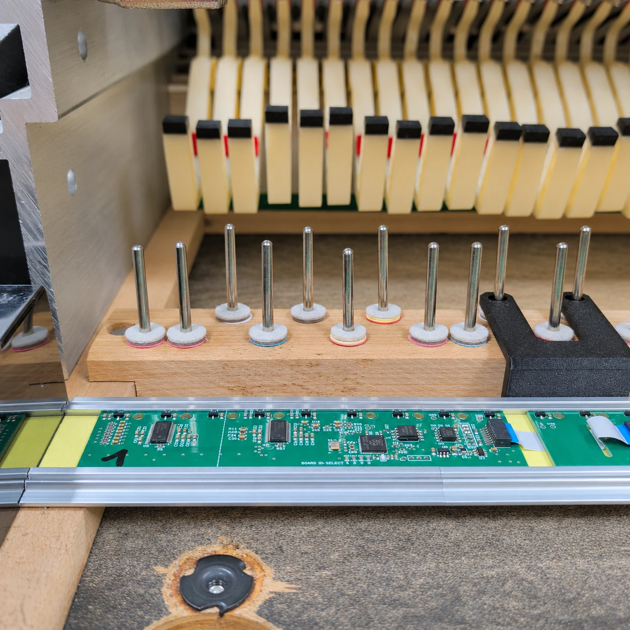
Keep the rail against both positioning jigs and the left cheekblock while aligning and fastening the boards.
Using one of the available mounting holes in the circuit board as a guide, drill a 1.5 mm hole through the aluminium profile. Vacuum up the metal shavings and clean the board and rail before continuing. Secure the board with one 2.3 × 5 mm countersunk screw.
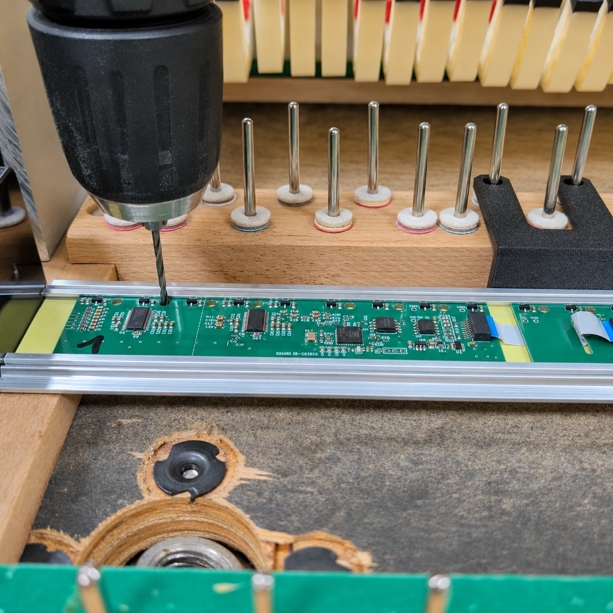
Align and secure the remaining sensorboards
Working from left to right, align each remaining sensorboard with the balance rail pins, distributing any deviations evenly. Keep the rail against the positioning jigs and the left cheekblock throughout.
Connect the sensorboard chain
Connect the free end of the 20 cm FPC cable prepared earlier to the IN connector on the last sensorboard, at the right-hand end of the rail.