Setup and calibration
About the screenshots
The screenshots in this manual show the desktop version of the WebUI, where the controls are displayed more clearly with less scrolling. You can also use the WebUI on a smartphone, but its layout may differ from the screenshots shown here.
The screenshots were taken using a USB connection. When you connect over Wi-Fi, the connection indicators may look different.
Check the electronics and open the WebUI
Check that all cables are correctly seated and oriented. Plug the supplied power supply into the socket on the front of the right-hand cheek block, then switch on the MIDIfy system using the power switch.
The LEDs on the sensorboards should flash rapidly for five seconds, then change to a running-light pattern.
On your computer, tablet or smartphone, connect to the Wi-Fi network created by the MIDIfy system:
- Network name: MIDIfy
- Password: midify617388
On a phone or tablet with mobile data, you must switch mobile data off before opening the WebUI.
Once connected to the MIDIfy Wi-Fi network and with mobile data switched off, open a web browser and go to http://192.168.4.1 to open the MIDIfy WebUI.
Check the system status
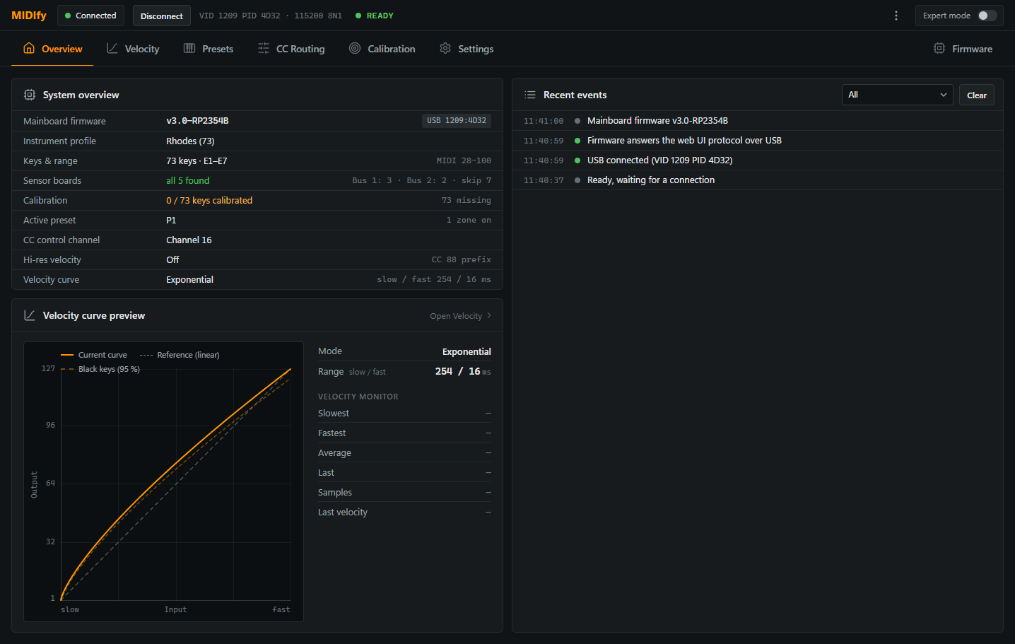
The screenshot below shows the expected overview when the system is ready. Check both indicators:
- The status in the top bar should read READY.
- Under Sensor boards, all boards required for your instrument should be found. The expected number depends on the instrument.
If both indicators match, the initial electronics check is complete.
Start the Rail Pre-Calibration Wizard
Open the Calibration tab in the WebUI and click Start Rail Pre-Calibration Wizard.
The wizard asks you to insert the reference keys for the selected instrument profile. Before inserting them, prepare these keys and fit their magnets as described below.
Prepare the reference keys
Fit magnets to the reference keys requested by the wizard so that you can use them to adjust the sensor rail height across the entire keyboard. The reference key selection depends on the instrument profile; the table below applies to a 73-key Rhodes.
For a 73-key Rhodes, use the following seven black reference keys. The key numbers are stamped into the keys. On most 73-key Rhodes pianos, the leftmost key is stamped 8; on others it is stamped 1. Use the corresponding row below:
| Number stamped on the leftmost key | Stamped reference key numbers |
|---|---|
| 1 | 5, 17, 29, 36, 46, 58, 70 |
| 8 | 12, 24, 36, 43, 53, 65, 77 |
Both rows identify the same physical keys. These are the instrument’s key numbers, not MIDI note numbers.
This reference key selection applies only to 73-key Rhodes models. The reference keys for 88-key Rhodes models have not yet been specified.
Mark the magnet holder mounting position
Place the magnet holder marking jig on the sensorboard with the marking screw tips pointing upwards. Locate the jig using its two preinstalled M3 countersunk screws. Choose two available holes that do not conflict with the screws already securing the sensorboard.
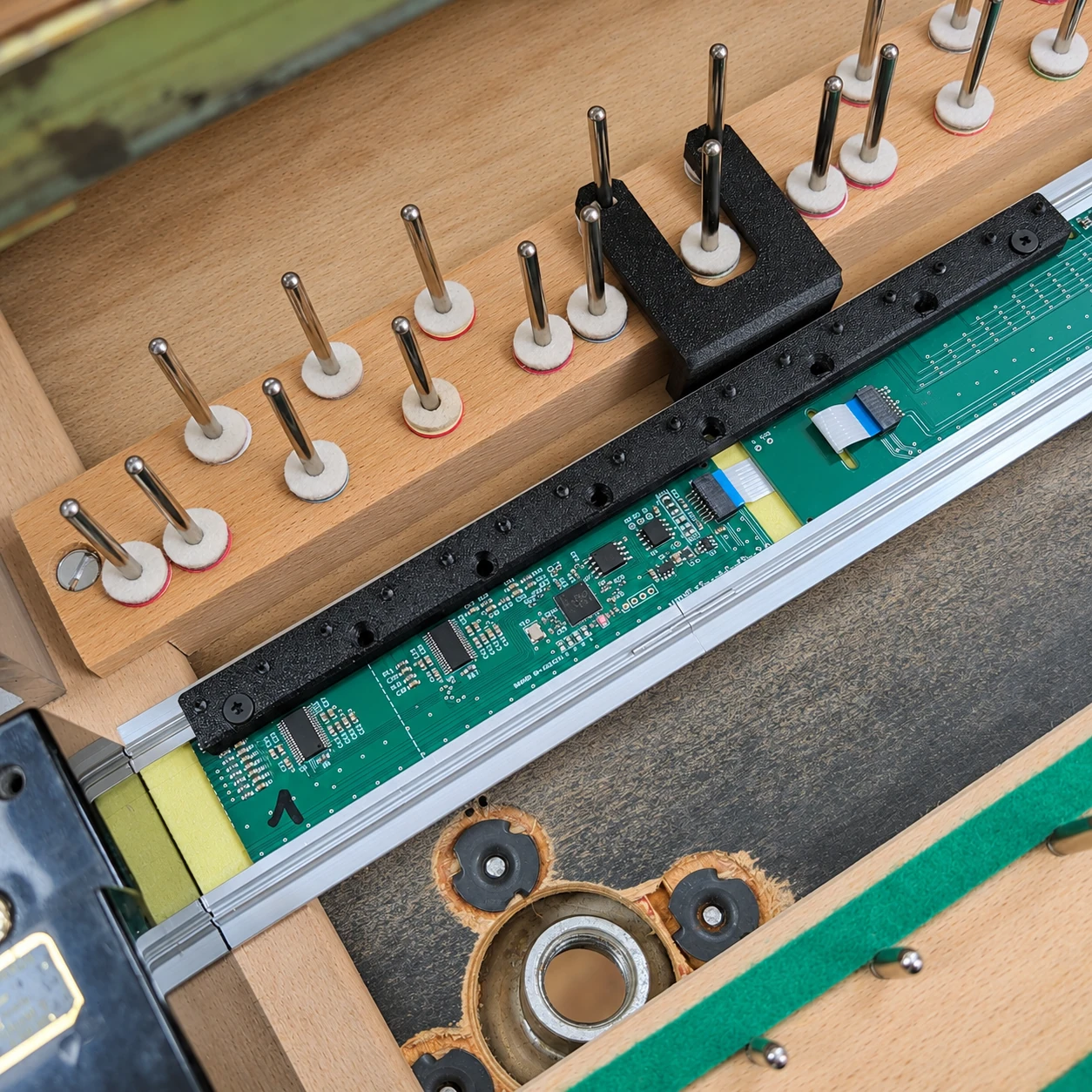
Work on one sensorboard at a time. On some instruments, the first sensorboard is shortened, so the jig extends beyond it. In this position, mark only keys belonging to that sensorboard. Do not use the overhanging part of the jig to mark keys belonging to the next sensorboard: the offset between boards would place the marks incorrectly.

Before marking keys on the next sensorboard, move the jig onto that board and align it with the board’s first sensor. A full-length sensorboard has 16 key positions. For now, mark only the selected reference keys; the same procedure can later be used for the remaining keys.

Insert the reference key in its normal position and press it down gently onto the jig to make a small indentation on the underside of the key.

Remove the key and locate the small indentation. This marks the mounting screw position for the magnet holder, not the position of the magnet itself.
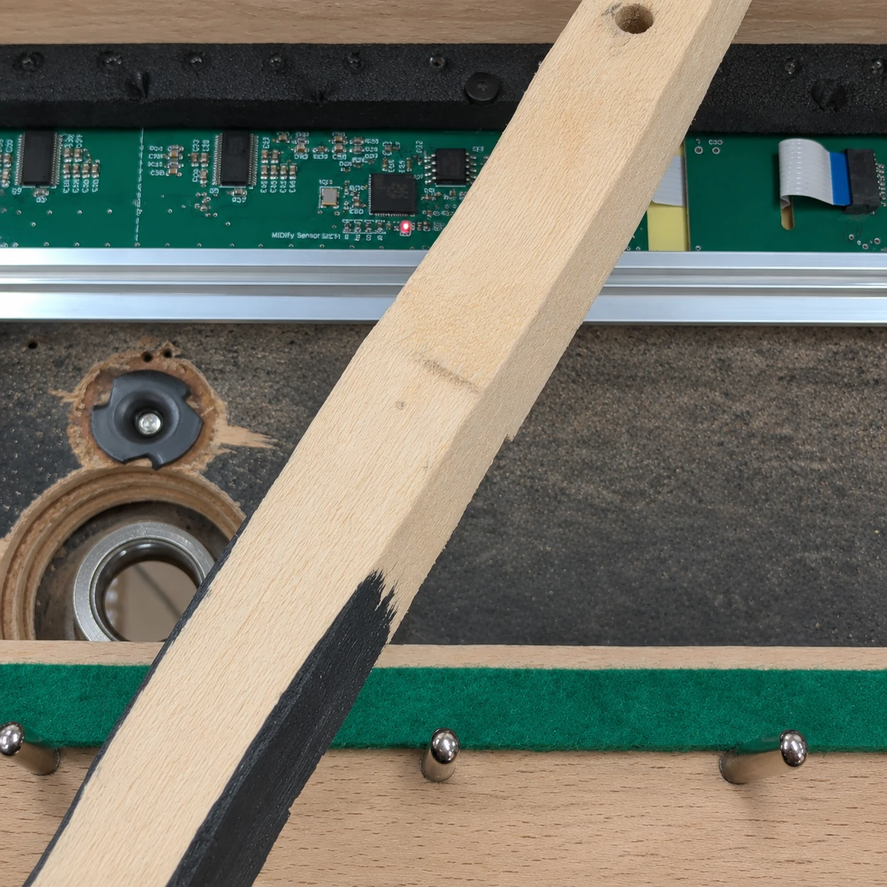
If the indentation is difficult to see, colour the screw tip with a marker and press the key onto it again to transfer the mark.
Mount the reference magnet holder
With the key removed, we recommend pre-drilling a 1.5 mm pilot hole at the marked position.
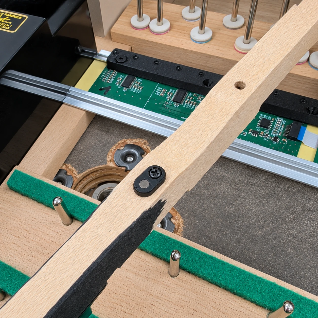
Use a black magnet holder for each black reference key. Insert a 2.3 × 12 mm countersunk screw through the holder and screw it into the marked position on the underside of the key.
If you ever need to insert a magnet into a holder, make sure its south pole faces the sensor. This applies to both black and white magnet holders.
Check the rail height with the reference keys
Once the magnets are fitted to all reference keys, place the keys back in their normal positions in the instrument. Click Continue to open Rail position. Leave all reference keys released briefly so that their rest positions can be measured.
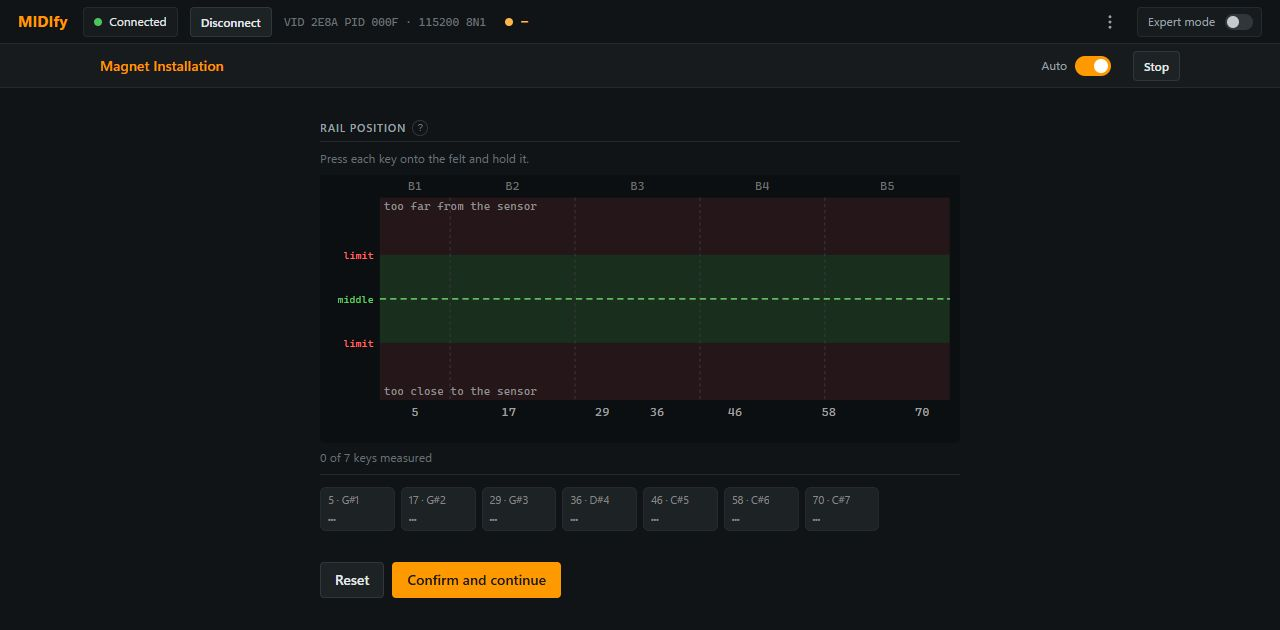
Press each reference key gently down, without pressing into aftertouch, and hold it briefly. The measurement is captured automatically.
The graph shows each reference key’s position within its usable range. A point above the green band means the magnet stays too far from the sensor; a point below it means the magnet comes too close. Green points and OK mean the position is within the usable range; red means it is outside. The points do not need to form a straight line. The summary shows how many reference keys have been measured.
Adjust the rail height
The example below shows all seven reference keys measured, with key 58 outside its usable range. The ▲0.4 indication asks you to raise the rail locally by approximately 0.4 mm into the usable range. ▲ means raise the rail; ▼ means lower it.

Raise the rail with card or spacers
Switch off the system and disconnect the power supply before fitting shims.
Use the height change shown in the wizard to choose a shim. For fine adjustments, cut shims from the supplied sheet of black card and place them under the rail. You can build up the height with layers of card. For a lift that would take a stack of card shims, the kit includes two 1.5 mm spacers.

When using a spacer at the centre, leave it whole and place it under the rail where it crosses the balance rail support.
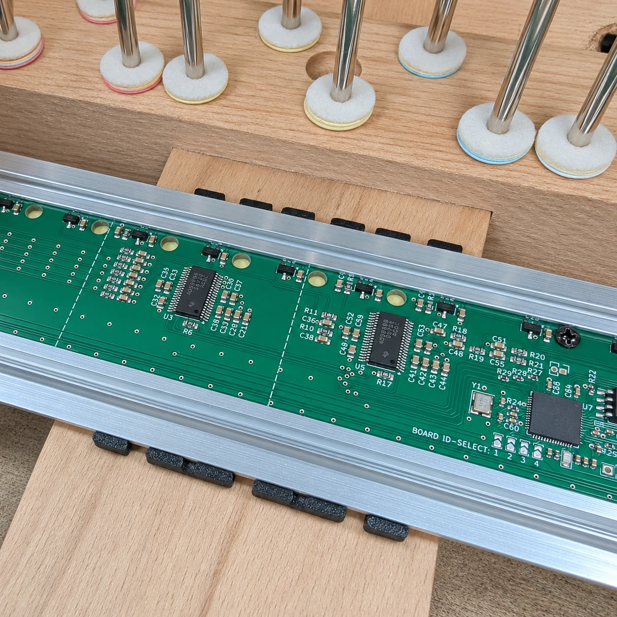
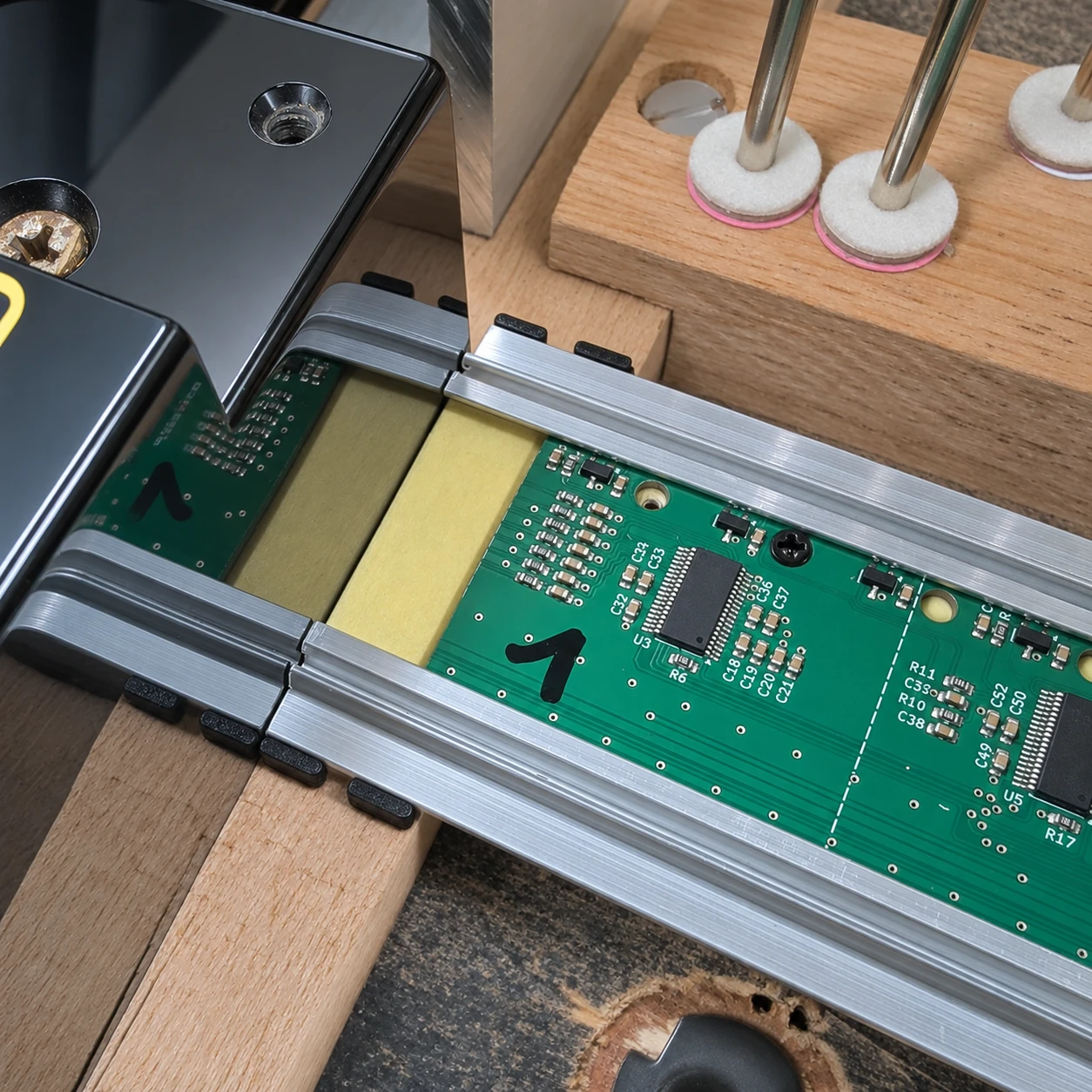
Cut the second spacer into individual pieces and place them under the left and right ends as needed. The photo below shows a piece under the left end, beside sensorboard 1.
Mark, drill and fasten the rail
- With the spacers in position beneath the rail, mark the aluminium directly above each spacer notch you will use for fastening. At the centre, the two marks are on opposite edges of the rail, as shown below.
- With the power still disconnected, unplug the 20 cm FPC cable from the right-hand sensorboard and lift the rail out of the instrument.
- Drill through the aluminium at the marks, keeping the drill clear of the sensorboards. Vacuum up the metal shavings and clean the rail and boards before refitting them.
- Set the rail back over the shims with the drilled holes aligned with the spacer notches. While the rail is still loose, reconnect the 20 cm FPC cable to IN on the right-hand sensorboard.
- Push the rail back against both positioning jigs and bring its left end against the left cheekblock. Hold it against all three stops while fastening it through the drilled holes with pan-head screws.

Reconnect the power supply and switch the system on. Recheck the rail height with the reference keys.
Release the reference key fully, then press it down and hold it again to take a new measurement. After changing the rail height, lift the affected reference keys out and put them back to reset their rest positions as well, then measure them again. Reset clears all reference-key measurements.
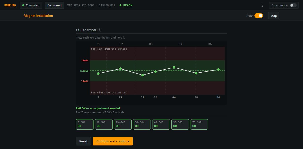
The screenshot below shows the result after correcting the rail height: all seven reference keys are within the green band, and the wizard displays Rail OK — no adjustment needed.
Prepare the remaining keys
Click Confirm and Continue at the bottom of the page to start the Magnet Install Wizard.
Remove the reference keys and place the magnet holder marking jig on the sensorboards again. Working one sensorboard at a time, mark all remaining keys and fit their magnet holders using the procedure described above. The reference keys already have their magnets fitted.
Use white magnet holders for white keys and black magnet holders for black keys.
Complete the magnet installation for the entire keyboard before starting calibration. Calibration begins with the lowest note, which is E on a 73-key Rhodes.
Calibrate the first key
On a 73-key Rhodes, calibration starts with E1, the lowest key. The calibration procedure is the same for every instrument.
Release all keys, then click Capture Rest to record the rest position.
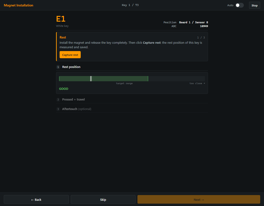 Press the selected key down until it just reaches the stop. Use the lightest pressure needed to reach this position, without pressing into the aftertouch range. Hold the key there and click Capture Press.
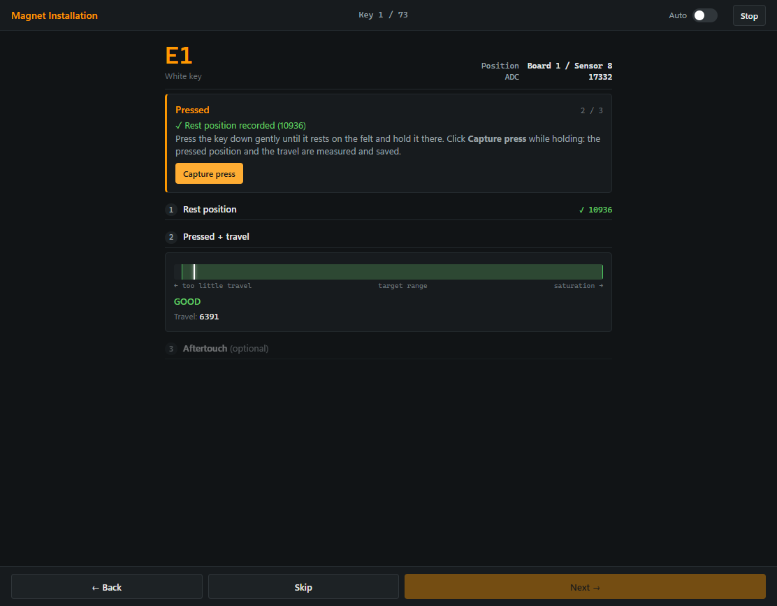 Press the key further into the felt until you reach what you consider maximum aftertouch. Hold this position and click Capture Aftertouch.
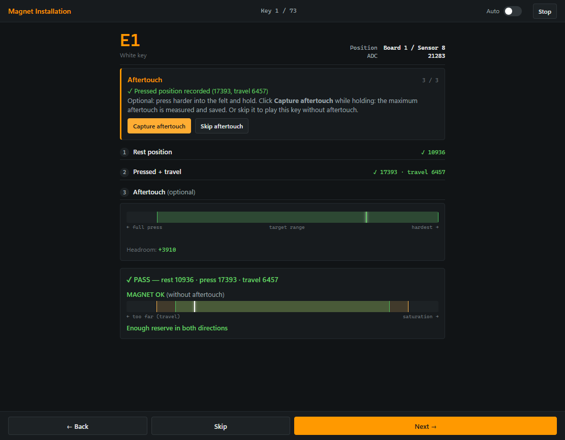
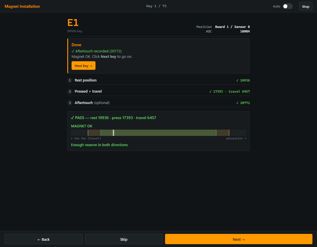
The first key is now calibrated.
Calibrate the remaining keys
Click Next to move to the next key. Repeat the same rest, press and aftertouch measurements for every key.
Optional: Auto mode
For your first calibration, we recommend leaving Auto switched off. The automatic sequence moves quickly and can be difficult to follow until you are familiar with the procedure.
To use Auto mode, enable Auto at the top right of the wizard. For each key, release it completely, press it gently to the stop without aftertouch, then press further to your maximum aftertouch position. The wizard captures each position automatically, briefly confirms the result and advances to the next key.
Complete the key calibration
Once all keys have been calibrated, the instrument is ready to play and outputs MIDI.
The next step is to calibrate the sustain pedal. Open the Calibration tab and select Sustain Pedal.
Troubleshooting: magnet too close or too far away
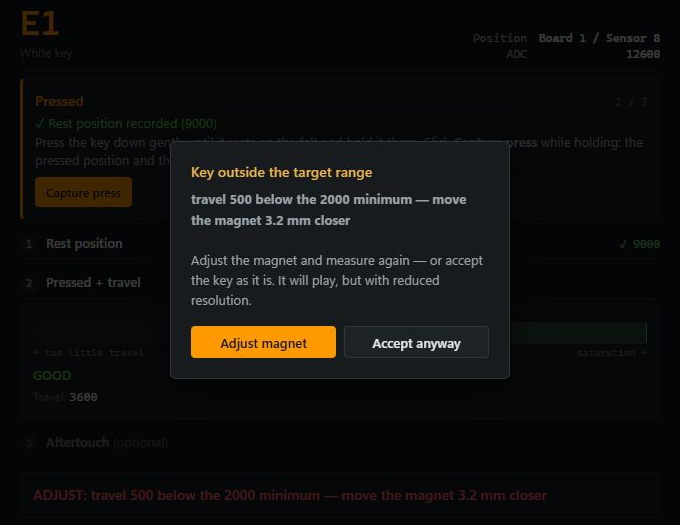
If the wizard reports Key outside the target range, check whether it asks you to move the magnet closer to the sensor or further away. Click Adjust magnet, correct the installation as described below and measure the key again.
Magnet too far from the sensor
For both black and white keys, place thin paper punchings between the magnet holder and the underside of the key to bring the magnet closer to the sensor. Use paper punchings intended for piano key levelling; these are not provided. Adjust the thickness as needed and secure the holder again.
Magnet too close to the sensor
For a black key, check the rail height at that key and lower the rail if necessary to increase the distance from the sensor. The distance from the sensor cannot be increased further by adjusting the black holder.
For a white key, replace the white magnet holder with a black magnet holder. Add paper punchings beneath the holder as needed until the magnet is within the usable range.
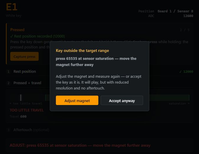
After changing a holder or adding paper punchings, repeat the key calibration from Capture Rest. If you change the rail height, recheck the reference keys and recalibrate the affected keys.
Calibrate the sustain pedal

In Calibration → Sustain Pedal, click Calibrate and follow the instructions:
- Release the pedal completely, then click Capture.
- Press the pedal all the way down, hold it there and click Capture.
- Move the pedal to the position at which you want the MIDI command to be sent, hold it there and click Capture.
You can now fine-tune the switching threshold. Click Save to confirm.
You can readjust the trigger point at any time under Calibration → Sustain Pedal.
Troubleshooting: sustain sensor range
A usable sensor range means that the raw reading changes clearly and smoothly as you move the pedal from fully released to fully pressed, without reaching a limit before the end of the movement.
If the magnet is too close to the sensor with the pedal released, loosen the magnet holder, place thin shims beneath it to increase the distance from the sensor, then secure it again.
If the magnet is too far from the sensor, move the sustain sensorboard upwards, closer to the magnet. This may require removing the instrument from the case to reach the mounting point. Alternatively, loosen the sensorboard, place thin shims beneath it to bring it closer to the magnet, then secure it again.
Switch off the system before changing the mounting. Afterwards, repeat the sustain-pedal calibration and check the switching point again.
Fine-tune the velocity curve
Continue with Velocity to adjust the velocity curve to your playing style.